Purification System design
PH Sensor
Since the PH is temperature dependent, at a different temperature, a solution will have a measurable change in PH. For this reason, we built a thermometer to make the PH testing more precise. The thermometer circuit diagram uses a 1N4148 diode as the temperature sensor, which has a negative temperature coefficient of -2 mV/C. To display the measured temperature, an Arduino is used and we can read the analogy value of temperature which can convert to digital number. Before we operate the thermometer, we need to calibrate it. To set the minimum level (0°C), place the diode into water filled with ice, and wait until the Arduino gives a stable value. To set maximum level (100°C), place diode into boiling water, wait until Arduino gives a stable number.
Once we get the water sample’s temperature, we can test its PH value. We built a simple PH meter, with TL082 (operation amplifier with a high impedance output), a PH probe (American Marine PINPOINT PH probe), volt meter and a 12-volt power supply. 12-volt source power the TL082, the PH probe connects to the non-inverting input, and connect the inverting input with output, which is directly proportional to PH scale, and read with the voltmeter.
Turbidity sensor
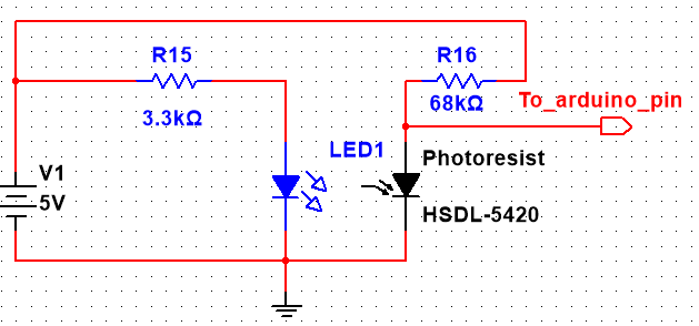
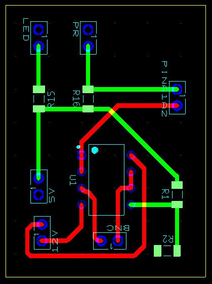
We built a simple circuit using photoresistor and LED to test turbidity, whole process would operate in a dark environment (Black box). LED would emit steady light, and photoresistor is a light-control variable resistor. The resistance decrease with increasing light intensity. The LED and photoresistor would be separated by the water sample. LED emits the light through water sample for one side, the photoresist would receive the light signal from LED on the other side. If the resistance of photoresistor is small, the water sample is more clear; otherwise, the water sample is cloudy. We used Arduino to read the how photoresistor change its resistance.


